ESP32로 장난감을 만든 다음 붙여있는 센서들의 input을 기초로 모델을 만들어 저장하려고 했는데, 가지고 있는 ESP32 보드들이 4MB PSRAM이 없는 WROOM 칩들을 사용하는 옛날 보드들이었습니다.
WROVER 버전들만 (4M / 8M / 16M)짜리 PSRAM이 있더군요.
가지고 있는 WROOM에도 SPIFFS 기능을 사용해서 화일을 쓰고 읽고 삭제할 수 있지만 크기가 많이 줄어듭니다.
실험용으로는 별 문제는 없겠지만 그래도 무척 아쉽군요.
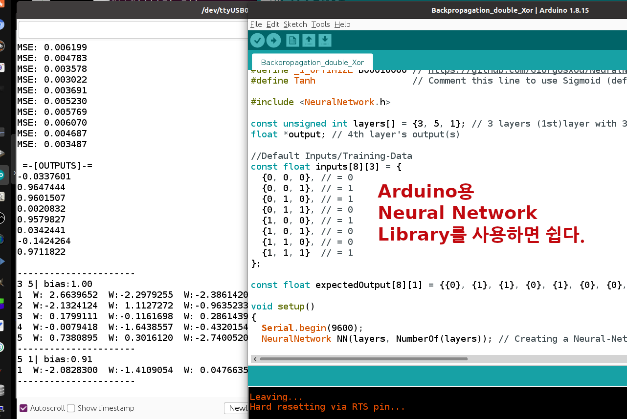
온라인에 ESP32로 AI를 사용하는 대부분의 경우는 Training을 PC에서 텐서플로같은 툴들을 사용해서 한 후 결과값만 코드로 옮겨서 사용하더군요. 단순한 센서의 값을 이용하는 경우의 대부분이 단순한 linear regression 문제라서 ESP32 자체적으로 금방 훈련도 될 것 같은데 원시적인 코딩이 불편한가 봅니다.
저도 원시적인 코딩이 귀찮아서 라이브러리들을 설치하게 되더군요.
SPIFFS 화일 작업 실험.
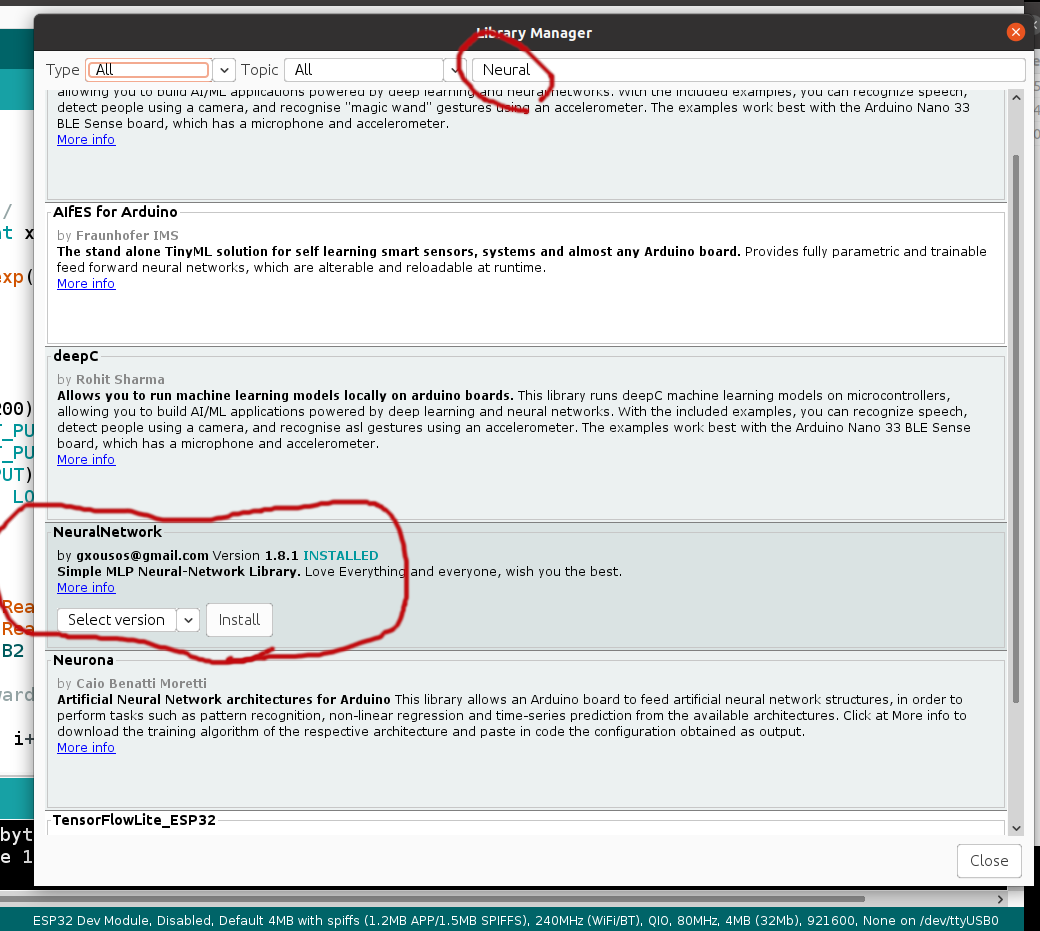
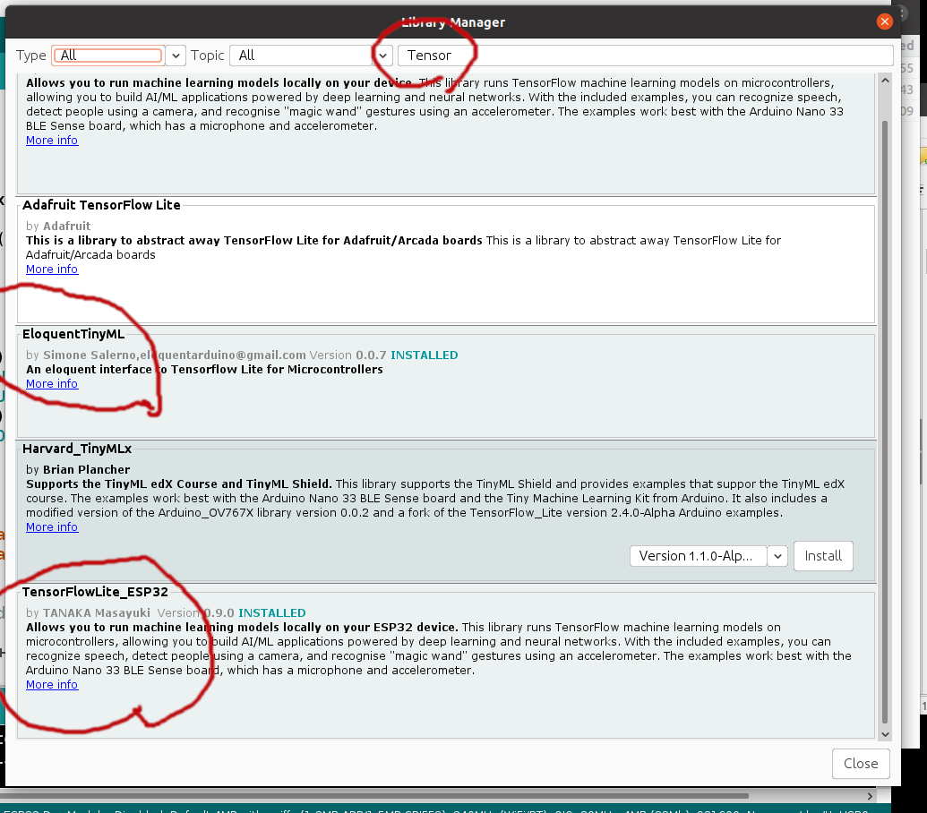
새로 설치한 ESP32에서 쓸 수 있는 인공지능용 라이브러리들. (key term : Neural, Tensor)
#include "SSD1306Wire.h" // legacy include: `#include "SSD1306.h"`
#define _CIRCLE_RAD 10
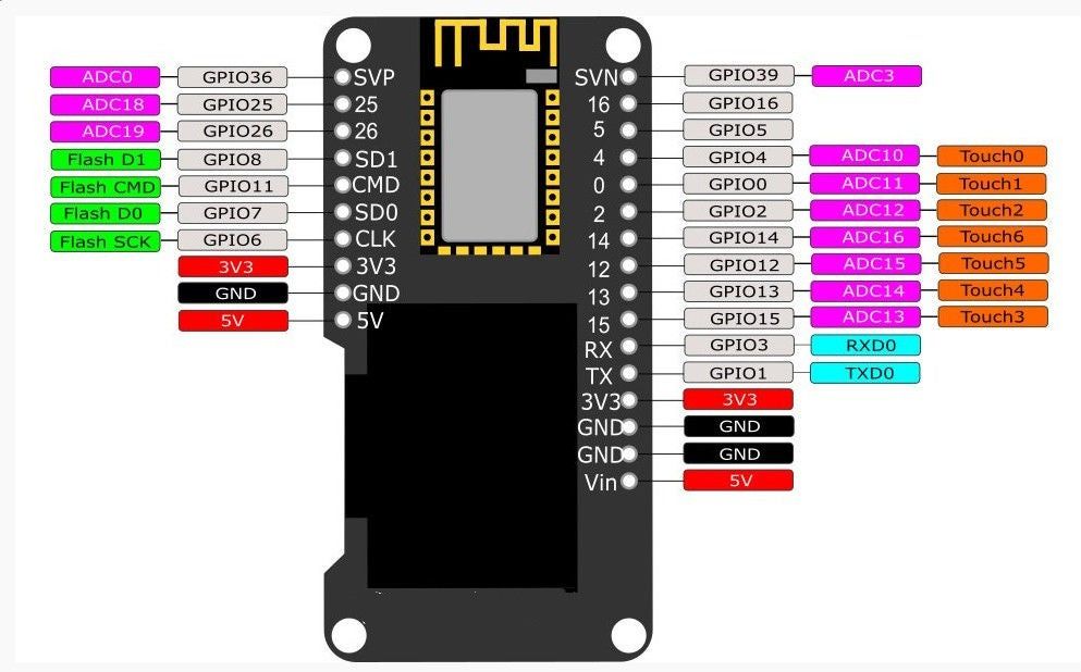
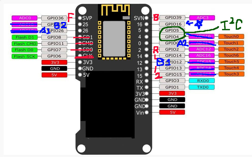
// (PIN NO) - 4 PhotoResistors (Front, Back, Left, Right)
const int prFrontPin = 36; // default A/D
const int prBackPin = 39; // default A/D
const int prLeftPin = 2; // (*) this analog port dies if Wifi is enabled
const int prRightPin = 14; // (*) this analog port dies if Wifi is enabled
// Also need to call on setup() to enable as A/D. "adcAttachPin(prLeftPin)";
// Also need to call on setup() to enable as A/D. "adcAttachPin(prRightPin)";
/* PROBLEM WITH ESP32 A/D : GPIO25, GPIO26, GPIO4, GPIO0 did not work as A/D */
// For Two Buttons
const int btnRUN = 13; // Run
const int btnTraining = 15; // Training Neural Network
bool IsRunning = false;
bool IsTraining = false;
// For TB6612FNG Motor Driver
// Currently problem with short number of pins, I will use GPIO16 for all following
// three pins on motor controller to put it HIGH,
// Will not use PWM, since this board sucks, and PWM has too much trouble.
// The OLED board that I used for this project is by far worst in all the ESP32 boards that I have used so far.
const int md_STBY_pin = 16; // Enables whole motor drive.
const int md_A_PWM_pin = 16; // Speed of Motor A
const int md_B_PWM_pin = 16; // Speed of Motor B
// I can disable motor A by in1 & in2 both LOW
const int md_AIN1_pin = 26; // Direction of Motor A
const int md_AIN2_pin = 0; // Direction of Motor A
// I can disable motor B by in1 & in2 both LOW
const int md_BIN1_pin = 12; // Direction of Motor B
const int md_BIN2_pin = 25; // Direction of Motor B
// (VALUES) 4 PhotoResistors (Front, Back, Left, Right)
int prFrontValue = 0;
int prBackValue = 0;
int prLeftValue = 0;
int prRightValue = 0;
SSD1306Wire display(0x3c, 5, 4);
int MotorTestL = 0; // 0 : stop, 1 : Forward, 2 : Backward
int MotorTestR = 0; // 0 : stop, 1 : Forward, 2 : Backward
const int WheelLeft = 32; // motor L on my design sheet
const int WheelRight = 27; // motor R on my design sheet
int r = 0; // Simple Counter to replace delay() in the main loop
String s; // Temporary string for general purpose
String sendbuff;
String commandstring;
String cs = ""; // Command String
String rs = ""; // Respond String = 'R' + Command String
char ReplyBuffer[] = "acknowledged"; // a string to send back
unsigned long preMillis = 0;
unsigned long curMillis = 0;
void drawTop(void) {
display.drawCircle(10, display.getHeight()/2, _CIRCLE_RAD);
display.display();
}
void drawBottom(void) {
display.drawCircle(50, display.getHeight()/2, _CIRCLE_RAD);
display.display();
}
void drawLeft(void) {
display.drawCircle(30, display.getHeight()-12, _CIRCLE_RAD);
display.display();
}
void drawRight(void) {
display.drawCircle(30, 10, _CIRCLE_RAD);
display.display();
}
void drawTest() {
display.init();
display.setContrast(255);
display.clear();
display.display();
delay(1000);
drawTop();
delay(500);
drawBottom();
delay(500);
drawLeft();
delay(500);
drawRight();
delay(500);
}
void IRAM_ATTR onRunPressed() {
if (IsRunning == false) {
Serial.println("RUN");
IsRunning = true;
} else {
Serial.println("OFF RUN");
}
MotorTestL += 1;
if (MotorTestL > 2) { MotorTestL = 0; }
}
void IRAM_ATTR onTrainingPressed() {
if (IsTraining == false) {
Serial.println("TRAINING");
IsTraining = true;
} else {
Serial.println("OFF TRAINING");
}
MotorTestR += 1;
if (MotorTestR > 2) { MotorTestR = 0; }
}
void turn_right() { // Turn Right
digitalWrite(md_AIN1_pin, HIGH);
digitalWrite(md_AIN2_pin, LOW);
digitalWrite(md_BIN1_pin, LOW);
digitalWrite(md_BIN2_pin, HIGH);
}
void turn_left() { // Turn Left
digitalWrite(md_AIN1_pin, LOW);
digitalWrite(md_AIN2_pin, HIGH);
digitalWrite(md_BIN1_pin, HIGH);
digitalWrite(md_BIN2_pin, LOW);
}
void move_forward() { //
digitalWrite(md_AIN1_pin, HIGH);
digitalWrite(md_AIN2_pin, LOW);
digitalWrite(md_BIN1_pin, HIGH);
digitalWrite(md_BIN2_pin, LOW);
}
void move_backward() { //
digitalWrite(md_AIN1_pin, LOW);
digitalWrite(md_AIN2_pin, HIGH);
digitalWrite(md_BIN1_pin, LOW);
digitalWrite(md_BIN2_pin, HIGH);
}
void wheel_stop() {
digitalWrite(md_AIN1_pin, LOW);
digitalWrite(md_AIN2_pin, LOW);
digitalWrite(md_BIN1_pin, LOW);
digitalWrite(md_BIN2_pin, LOW);
}
void setup() {
r = 0;
pinMode(btnRUN, INPUT); // BUTTON B1
pinMode(btnTraining, INPUT); // BUTTON B2
attachInterrupt(btnRUN, onRunPressed, RISING);
attachInterrupt(btnTraining, onTrainingPressed, RISING);
pinMode(md_STBY_pin, OUTPUT); // 16; // (6 will CRASH) Enables whole motor drive.
pinMode(md_AIN1_pin, OUTPUT); // 26;// Direction of Motor A
pinMode(md_AIN2_pin, OUTPUT); // 0; // Direction of Motor A
// pinMode(md_A_PWM_pin, OUTPUT);// 16; // Speed of Motor A
pinMode(md_BIN1_pin, OUTPUT); // 12;// Direction of Motor A
pinMode(md_BIN2_pin, OUTPUT); // 25; // Direction of Motor A
// pinMode(md_B_PWM_pin, OUTPUT);// 16; // Speed of Motor A
Serial.begin(112500);
drawTest();
adcAttachPin(prLeftPin);
adcAttachPin(prRightPin);
digitalWrite(md_STBY_pin, HIGH); // it will make ON for both PWMA, PWMB also
// digitalWrite(md_A_PWM_pin, HIGH);
// digitalWrite(md_B_PWM_pin, HIGH);
move_forward(); delay(1000);
wheel_stop(); delay(1000);
move_backward(); delay(1000);
wheel_stop(); delay(1000);
turn_right(); delay(1000);
wheel_stop(); delay(1000);
turn_left(); delay(1000);
wheel_stop(); delay(1000);
}
void loop() {
r++;
if (r > 650000){ // THIS IS DESCENT DELAY // about 1 sec
prFrontValue = analogRead(prFrontPin); // delay in between reads for stability
prBackValue = analogRead(prBackPin); // delay in between reads for stability
prLeftValue = analogRead(prLeftPin); // delay in between reads for stability
prRightValue = analogRead(prRightPin); // delay in between reads for stability
// delay(50); // delay in between reads for stability
s = " ";
s += prFrontValue;
s += ", ";
s += prBackValue;
s += ", ";
s += prLeftValue;
s += ", ";
s += prRightValue;
Serial.println(s);
r = 0;
}
}