이 문서는 우리가 만든 프로그램이 어떻게 작동하는지 단계별로 설명합니다. 카메라에서 들어온 단일 스테레오 이미지가 화면에 3D 점으로 찍히기까지의 전체 여정을 추적해 보겠습니다.

🏛️ 핵심 아키텍처: 두 개의 스레드

가장 먼저, 우리 프로그램이 두 개의 병렬 스레드에서 실행된다는 점을 이해하는 것이 중요합니다. 이것이 바로 프로그램을 빠르게 만드는 핵심입니다. 하나의 스레드가 무거운 수학 연산을 처리하는 동안, 다른 스레드는 그림을 그립니다.

  1. VO 스레드 (VO Thread - "공장")
    • 파일: src/main.rs
    • 함수: run_live_vo_thread
    • 임무: 모든 힘든 작업을 수행합니다. 카메라와 통신하고, 비용이 많이 드는 OpenCV 함수(이미지 보정, 스테레오 계산, 특징점 검출)를 실행하며, 3D 포인트와 카메라 자세(Pose)를 계산합니다. 이 스레드의 유일한 목표는 "결과물"을 생산하는 것입니다.
  2. 메인 스레드 (Main Thread - "전시장")
    • 파일: src/main.rs
    • 함수: main
    • 임무: 모든 그리기를 수행합니다. OpenGL 창과 OpenCV imshow 창을 생성합니다. 99%의 시간을 이전에 마지막으로 받은 결과를 다시 그리고 새로운 결과를 기다리는 데 사용합니다. 이 스레드는 절대로 무거운 계산을 해서는 안 됩니다. 그렇지 않으면 화면이 멈출 것입니다.
  3. MPSC 채널 (The "컨베이어 벨트")
    • 코드: let (tx, rx) = mpsc::channel::<(...)>();
    • 임무: 두 스레드를 연결하는 고속 "컨베이어 벨트"입니다.
    • **tx (Transmitter)**는 VO 스레드에 있습니다. 최종 결과물을 보냅니다.
    • **rx (Receiver)**는 메인 스레드에 있습니다. 결과물을 받습니다.

🗺️ 파트 1: 프레임의 여정 (VO 스레드)

run_live_vo_thread 함수 내부에서 단일 프레임이 처리되는 단계별 과정입니다.

1단계: 초기화 (최초 1회 실행)

루프가 시작되기 전에 모든 것을 준비합니다:

  1. load_calibration(): stereo_params_PC.yml 파일을 엽니다. 이 함수는 카메라를 정의하는 모든 핵심 매트릭스(K1, D1, R1, P1, Q 등)를 로드합니다. 또한 P1 매트릭스와 image_height를 기반으로 카메라의 *실제 수직 화각(FOV)*을 계산합니다 (약 30.15도임을 확인했습니다).
  2. init_rectification(): 로드한 보정 데이터를 사용하여 두 개의 "조회 테이블"(RectificationMaps)을 미리 계산합니다. 이 맵은 원본 이미지를 *왜곡(warp)*시켜 완벽하게 정렬되고 왜곡이 제거된 이미지로 만드는 데 사용됩니다.
  3. cap_combined.set(...): 카메라에게 320x240 이미지 두 개가 나란히 붙어 있는 640x240 크기의 단일 와이드 이미지를 보내도록 요청합니다.

2단계: 획득 및 분할 (루프 시작)

  1. cap_combined.read(): 카메라에서 하나의 와이드 프레임을 가져옵니다.
  2. Mat::roi(): roi_l(왼쪽 영역)과 roi_r(오른쪽 영역)을 사용하여 이 와이드 프레임을 curr_left_gray와 curr_right_gray라는 두 개의 개별 Mat 객체로 "잘라냅니다".

3단계: 이미지 보정 (첫 번째 "마법")

스테레오 비전에서 가장 중요한 단계입니다.

  • imgproc::remap(): 이 함수를 두 번 호출합니다. 1단계에서 미리 계산한 RectificationMaps를 사용하여 curr_left_gray와 curr_right_gray의 "왜곡을 풉니다".
  • 결과: rectified_left와 rectified_right 이미지를 얻습니다. 이 이미지들은 이제 완벽하게 정렬되어, 마치 "완벽한" 핀홀 카메라로 찍은 것처럼 되었습니다. 이 과정은 다음 단계가 작동하기 위해 필수적입니다.

4단계: 시차(Disparity) 및 3D 복원

  1. compute_disparity_map(): 두 개의 보정된 이미지를 StereoSGBM 알고리즘에 입력합니다. 알고리즘이 두 이미지를 비교하여 disparity_map_curr(시차 맵)를 생성합니다. 이것은 각 픽셀의 색상깊이를 나타내는 2D 이미지입니다 (밝을수록 가까움).
  2. calib3d::reproject_image_to_3d(): 이것이 두 번째 "마법" 단계입니다. 2D 시차 맵과 Q 매트릭스(보정 파일에서 로드한)를 이 함수에 전달합니다. 이 정보는 2D 깊이 이미지를 완전한 3D 포인트 클라우드(point_cloud_curr)로 변환하는 데 사용됩니다. 이제 각 픽셀은 밀리미터(mm) 단위의 실제 (X, Y, Z) 좌표를 갖게 됩니다.

5단계: Visual Odometry (우리는 어디에 있는가?)

이 단계는 이전 프레임 대비 우리가 어떻게 움직였는지 파악합니다.

  1. detector.detect_and_compute(): rectified_left 이미지에서 수백 개의 "키포인트"(코너나 흥미로운 질감 등)를 찾습니다.
  2. knn_match(): 이번 프레임의 키포인트와 이전 프레임에서 저장해 둔 키포인트(prev_frame_data)를 비교합니다. 이를 통해 수백 개의 2D 매칭 쌍을 얻습니다.
  3. 3D 대응점 생성: 모든 2D 매칭 쌍을 반복하면서, 각 쌍에 대해 현재 point_cloud_curr와 이전 prev_frame_data에서 3D (X,Y,Z) 좌표를 조회합니다. 이제 (3D 공간의 A 지점, 3D 공간의 B 지점) 쌍의 목록을 갖게 됩니다. 이것이 우리의 correspondences 리스트입니다 (예: "70개의 유효한 3D 대응점").
  4. odom.update(): 이 리스트를 Odometry 클래스로 보냅니다. 이 클래스는 RANSAC 알고리즘을 사용하여 이 모든 점들의 움직임을 가장 잘 설명하는 최적의 회전(R) 및 이동(t) 값을 찾습니다. 그런 다음, 이 움직임을 global_rotation과 global_translation에 누적하여 처음 시작점으로부터의 현재 위치를 계속 추적합니다.

6단계: 렌더러를 위한 처리 (Vec<f32> 생성)

이제 최종 결과물을 만듭니다. point_cloud_curr의 모든 픽셀을 반복합니다:

  1. (X,Y,Z) 가져오기: (mm 단위의) (X, Y, Z) 값을 가져옵니다.
  2. 필터링: 유효한 값인지 확인합니다: if z_cv.is_finite() && z_cv > 300.0 && z_cv < 10000.0. 이것이 불량 데이터를 제거하는 30cm ~ 10m "깊이 필터"입니다.
  3. 좌표계 변환: OpenCV 좌표계에서 OpenGL 좌표계로 변환하기 위해 Y축과 Z축을 뒤집습니다 (y_gl = -y_cv, z_gl = -z_cv).
  4. 색상 계산: 깊이에 따라 흰색(가까움)에서 어두운 회색(멈)으로 변하는 그레이스케일 색상을 계산합니다.
  5. points_vec.push(...): 6개의 숫자(x_gl, y_gl, z_gl, r, g, b)를 최종 Vec<f32>에 추가합니다.

7단계: 텍스트 그리기 및 전송

  1. put_text(): 사용자 정의 설정(빨간색, 0.8 크기 등)을 사용하여 point_count, centroid, global_translation 값을 tracking_viz 이미지에 그립니다.
  2. data_tx.send(...): 세 가지 결과물을 하나로 묶어 "컨베이어 벨트"를 통해 메인 스레드로 전송합니다:
    • tracking_viz (텍스트가 그려진 이미지)
    • points_vec (거대한 3D 포인트 목록)
    • (global_rot, global_trans) (최종 자세)

이제 VO 스레드의 루프가 완료되었으며, 즉시 2단계로 돌아가 다음 프레임 처리를 시작합니다.


📦 파트 2: 데이터 수신 및 사용 (메인 스레드)

이 부분은 훨씬 간단하고 빠릅니다. main 함수의 이벤트 루프입니다.

1단계: "컨베이어 벨트" 확인

  • rx.try_recv(): 메인 스레드에서 가장 중요한 부분입니다. VO 스레드에서 새 패키지가 도착했는지 "컨베이어 벨트"를 살짝 엿봅니다.
    • Ok(...)일 경우: 새 패키지가 도착했습니다! if 블록 안으로 들어갑니다.
    • Err(...)일 경우: 새 패키지가 없습니다. if 블록 전체를 건너뛰고 이전 데이터를 다시 그립니다. 이것이 바로 VO 스레드가 느리더라도 3D 뷰가 여전히 부드럽게 느껴지는 이유입니다.

2단계: 모든 상태 업데이트 (새 패키지 도착 시)

  1. highgui::imshow(...): tracking_img를 즉시 OpenCV 창에 표시합니다.
  2. point_cloud.update_data(points_vec): 전체 Vec<f32>를 PointCloud 객체로 보냅니다. 이 객체는 모든 새 정점 데이터를 GPU의 VBO(Vertex Buffer Object)에 업로드합니다.
  3. 자세(Pose)를 뷰 매트릭스(View Matrix)로 변환: 이것이 "1인칭" 카메라의 핵심 로직입니다:
    • vo_rot_na와 vo_trans_na를 cgmath 타입(r_gl, t_gl)으로 변환합니다.
    • 카메라의 3D 위치를 vo_camera_pos_gl에 저장합니다.
    • 이들을 4x4 vo_pose_matrix로 결합합니다.
    • 이 매트릭스를 **역(inverse)**변환하여 **vo_view_matrix**를 만듭니다. (이것은 3D 그래픽스의 핵심 개념입니다: "뷰" 매트릭스는 항상 월드 공간에서의 카메라 "자세"의 역행렬입니다.)

3단계: 장면 렌더링 (매 루프마다 실행)

  1. let view = vo_view_matrix;: 방금 계산한 (또는 새 패키지가 없으면 이전의) vo_view_matrix를 사용하도록 렌더러에 지시합니다.
  2. let proj = perspective(...): 시작할 때 계산한 올바른 FOV를 사용하여 투영 매트릭스를 생성합니다.
  3. let model_matrix = Matrix4::identity();: 포인트 클라우드를 원점(0,0,0)에 그리도록 렌더러에 지시합니다.
  4. point_cloud.draw(...): 이 함수는 GPU에게 "VBO에 있는 모든 점들을 이 model_matrix, view 매트릭스, proj 매트릭스를 사용해서 그려라"고 명령합니다.
  5. axis.draw(...): 월드 좌표축에 대해서도 동일한 작업을 수행합니다.
  6. windowed_context.swap_buffers(): 최종 이미지를 화면에 표시합니다.

🚀 파트 3: "최종 데이터" 활용하기

이제 매 프레임마다 세 가지 매우 가치 있는 데이터를 생성하는 프로그램을 갖게 되었습니다. 이 데이터는 VO 스레드의 data_tx.send(...) 호출 직전에 존재합니다.

  1. point_cloud_curr (원본 Mat): (유효하지 않은 값 포함) 320x240 = 76,800개의 포인트로 구성된 전체 3D 포인트 클라우드 (OpenCV Mat 형식).
  2. points_vec (필터링된 Vec<f32>): 깊이 값으로 필터링된 깨끗한 포인트 클라우드 (약 ~29,000개 포인트), OpenGL에서 렌더링 준비 완료된 형식.
  3. global_translation (자세): 카메라의 (X, Y, Z) 위치를 밀리미터(mm) 단위로 담고 있는 na::Vector3<f32>.

이 데이터를 활용하는 3가지 아이디어는 다음과 같습니다:

아이디어 1: 경로 저장하기 (간단한 SLAM)

카메라가 이동한 경로를 파일에 저장하여 시각화할 수 있습니다.

  • run_live_vo_thread (루프 시작 전):

      use std::io::Write; // 상단에 추가

      let mut camera_path: Vec<na::Vector3<f32>> = Vec::new();


  • run_live_vo_thread (루프 내부, odom.update 호출 후):

      let (global_rot, global_trans) = odom.get_pose();

      camera_path.push(global_trans.clone());


  • 맨 마지막 (루프 종료 후):

      // 프로그램이 종료될 때 경로를 파일로 저장
      let mut file = std::fs::File::create("path_output.txt")?;
      for point in camera_path {
          writeln!(file, "{} {} {}", point.x, point.y, point.z)?;
      }
      println!("Saved camera path to path_output.txt");


아이디어 2: 간단한 로봇 내비게이션

자세(pose) 정보를 기초적인 자동화에 사용할 수 있습니다.

  • run_live_vo_thread (루프 내부, odom.update 호출 후):

      let (global_rot, global_trans) = odom.get_pose();

      // 예: 로봇이 1미터(1000mm) 이상 움직였는지 확인
      if global_trans.norm() > 1000.0 {
          println!("경고: 시작 지점에서 1미터 이상 벗어났습니다!");
          // (여기에 로봇 모터에 "후진" 또는 "회전" 같은
          //  명령을 보내는 코드를 추가할 수 있습니다)
      }


아이디어 3: 3D 스캔 파일(.xyz) 생성하기

3D 환경을 저장하여 MeshLab 같은 프로그램에서 볼 수 있습니다.

  • run_live_vo_thread (루프 종료 후):

    // 참고: 이것은 *마지막* 프레임만 저장합니다. 실제 3D 스캐너는
      // *모든* 프레임의 포인트들을 자세(pose)를 이용해 결합해야 합니다.

      // 이미 만들어둔 `points_vec`를 사용할 수 있습니다.
      use std::io::Write; // 상단에 추가 (이미 했다면 생략)
      let mut file = std::fs::File::create("scan.xyz")?;

      // `points_vec`는 [x,y,z,r,g,b, x,y,z,r,g,b, ...] 형식입니다.
      // 한 번에 6개 항목씩 건너뜁니다.
      for chunk in points_vec.chunks_exact(6) {
          let x = chunk[0];
          let y = chunk[1];
          let z = chunk[2];
          let r = (chunk[3] * 255.0) as u8; // 색상 값을 0-255 범위로 변환
          let g = (chunk[4] * 255.0) as u8;
          let b = (chunk[5] * 255.0) as u8;

          // "XYZRGB" 형식으로 저장
          writeln!(file, "{} {} {} {} {} {}", x, y, z, r, g, b)?;
      }
      println!("Saved last point cloud to scan.xyz");


'Depth Map with Dual CAM' 카테고리의 다른 글

초저가 USB 쌍안 캠을 사용한 Depth Tracking  (0) 2021.07.12
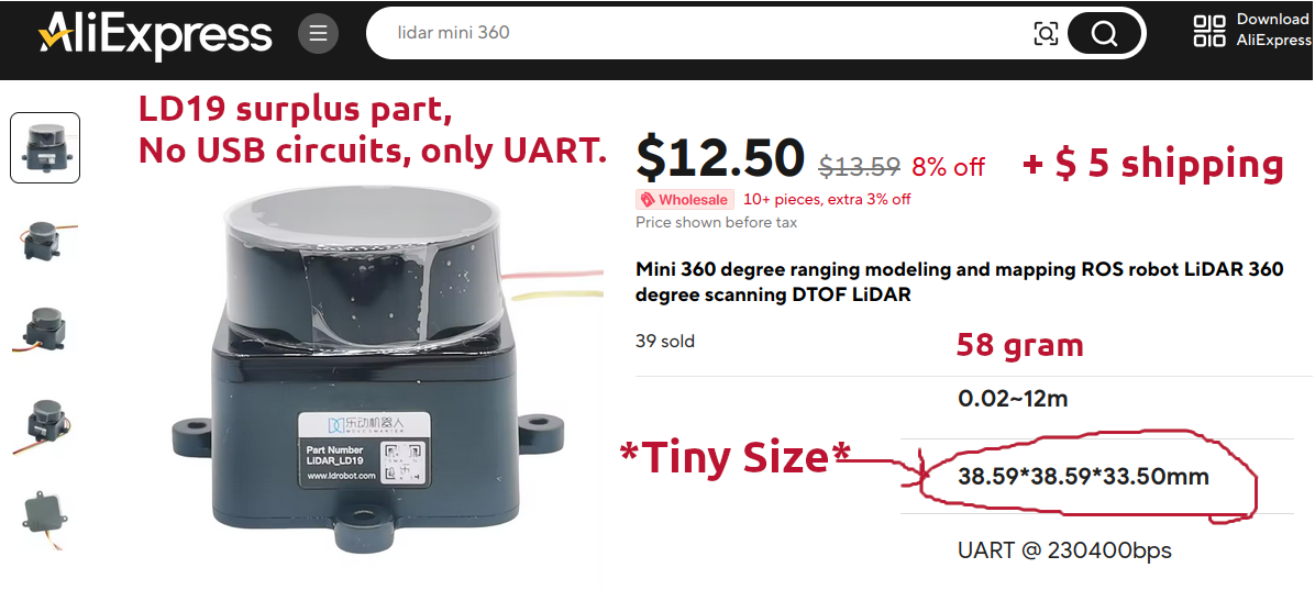
오늘 도착한 mini 2D lidar입니다. 가격은 $12.50 + $5 shipping 인데, 하루만에 실험에 성공했습니다.
옛날에 쓰던 라이다와 크기를 비교하니 아주 확연히 다르네요. 이 정도 크기라면 드론에 직접 올리는 것도 가능해 보입니다.


깃헙에 찾은 샘플 테스팅 코드 : https://github.com/halac123b/Visualize-data-from-Lidar-LD19_Matplotlib-Python


GitHub - halac123b/Visualize-data-from-Lidar-LD19_Matplotlib-Python

Contribute to halac123b/Visualize-data-from-Lidar-LD19_Matplotlib-Python development by creating an account on GitHub.

github.com

문제는 첫 실험 코딩이 matplotlib를 사용해서 엄청 느리기 때문에 PyQtGraph 라이브러리로 바꿔서 코딩해야 할 듯 합니다.


이건 나의 실험 케이스 :

   Platform : Orange Pi 5, on UART #0 ( /dev/ttyS0 ) @ 230400 bps.

     Speed control : PWM1_M2, pin # 26, which uses /sys/class/pwm/pwmchip0/

        Then use the following command to make pwm1 output a 50Hz square wave (please
        switch to the root user first, and then execute the following command)
        root@o5bot:~# echo 0 > /sys/class/pwm/pwmchip0/export
        root@o5bot:~# echo 20000000 > /sys/class/pwm/pwmchip0/pwm0/period
        root@o5bot:~# echo 1000000 > /sys/class/pwm/pwmchip0/pwm0/duty_cycle
        root@o5bot:~# echo 1 > /sys/class/pwm/pwmchip0/pwm0/enable


Lazarus IDE를 사용해서 Object Pascal로 프로그래밍 하기. 

(사용 라이브러리 : BGRABitmap )


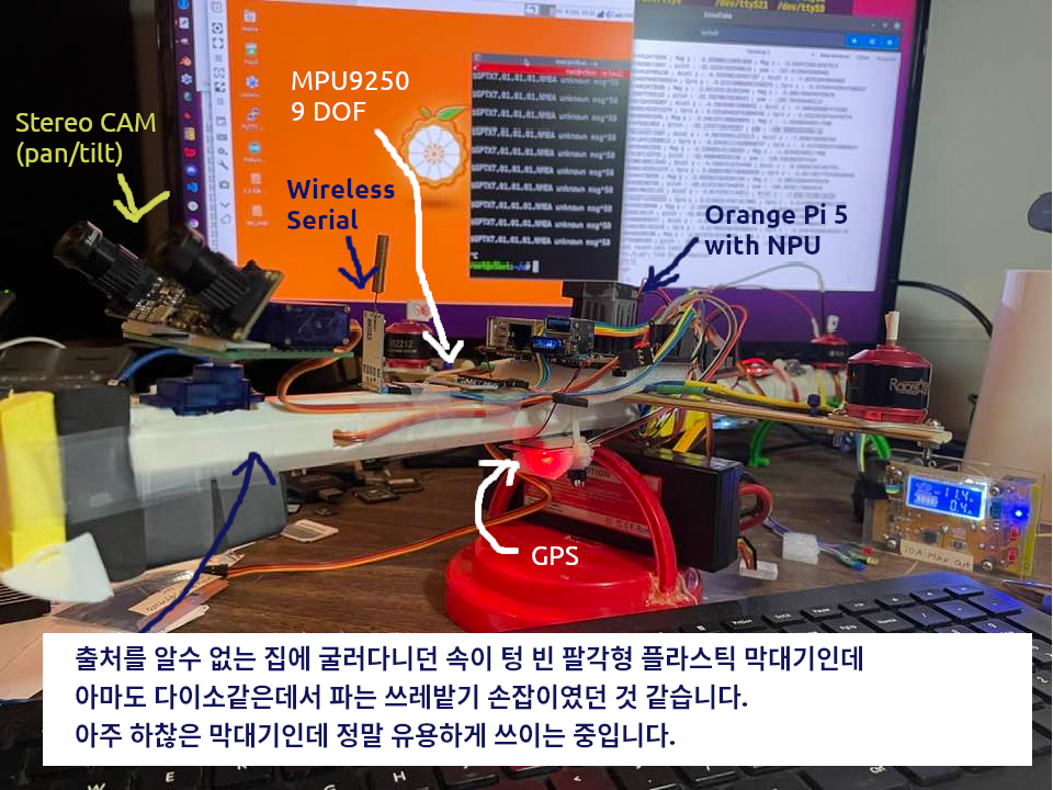
이 기체는 6 TOPS의 속도의 NPU를 장착하고 있어서 인공지능 기능이 가능합니다.

가령 stereo camera로부터 추출해 내는 3D Depth와 YOLOv8이 가능합니다.


stereo camera로부터 추출해 내는 3D Depth (CPU의 10%사용)
YOLOv5로 사물인식 영상 (NPU의 33%사용)


'M.A.R. (Machine of Attack & Return)' 카테고리의 다른 글

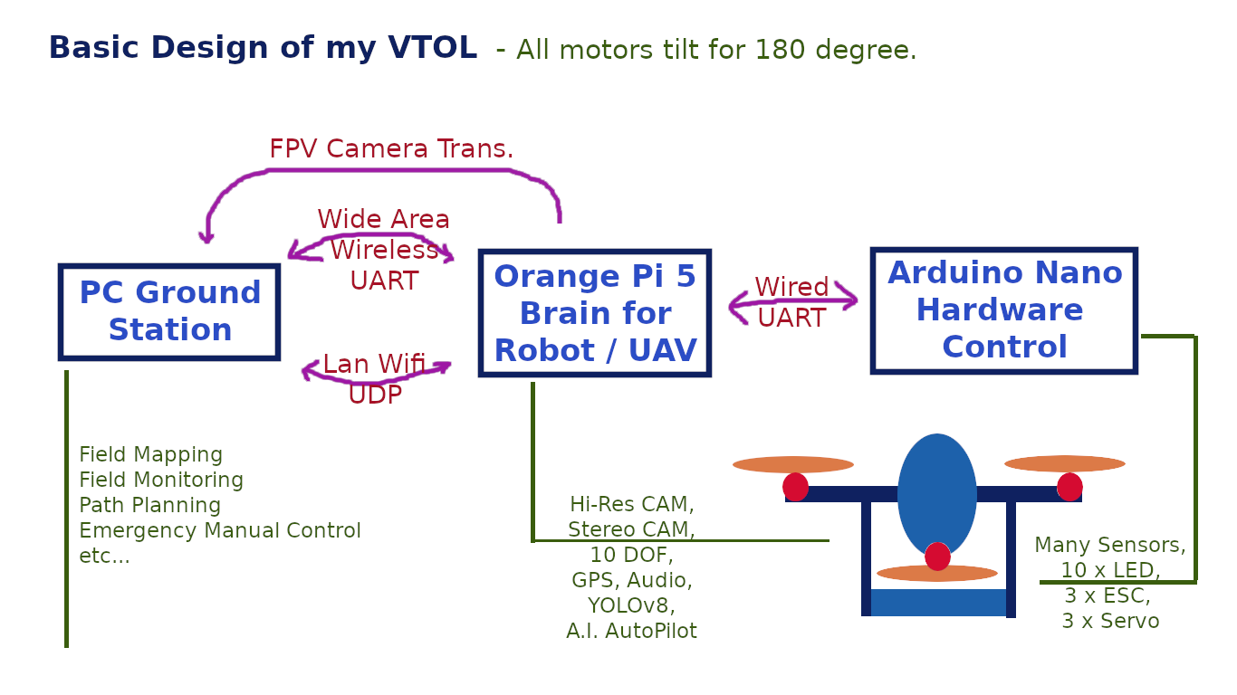
전체 계획의 간략한 도면  (0) 2023.10.03

만들다 보니 지금 드론 자체의 무게만 해도 330g 짜리 배터리까지 합치면 거의 1kg이 넘어간다.

어쩌면 아마도 지금 달아놓은 모터로는 뜨지도 못할 가능성까지 있다.

거기에 지금 필요하다고 생각되는 Payload를 2.5kg으로 추가로 잡는다면 드론 모터부터 바꿔야 할 지 모른다.

그래서 모터 찾는 방법들을 찾아보았다.

넉넉잡고 드론까지 합쳐서 4kg의 Load를 날릴 수 있는 모터를 찾아야겠다.

https://robu.in/selecting-quadcopter-motor-a-detailed-guide-2021/

https://www.alibaba.com/product-detail/MOTORS-big-thrust-brushless-drone-OEM_1600799748053.html


Motors Big Thrust Brushless Drone Oem T-motor Aircraft 10kg Payload Motor - Buy Buy 24v Dc Motor,Oem T-motor,Brushless Dc Motor

Motors Big Thrust Brushless Drone Oem T-motor Aircraft 10kg Payload Motor , Find Complete Details about Motors Big Thrust Brushless Drone Oem T-motor Aircraft 10kg Payload Motor,Buy 24v Dc Motor,Oem T-motor,Brushless Dc Motor Price 10 Volt Medical Bldc Dc

www.alibaba.com

https://www.aliexpress.us/item/3256805045951351.html?spm=a2g0o.order_list.order_list_main.5.14af1802RRDMP2&gatewayAdapt=glo2usa 


https://www.aliexpress.us/item/3256805045951351.html?gatewayAdapt=glo2usa&spm=a2g0o.order_list.order_list_main.5.14af1802RRDMP2


www.aliexpress.us


Orange Pi 5에서 모터와 기타 단순 관리용 서브모듈로 사용하는 Arduino Nano와의 시리얼 통신용 코드.

이 방식은 아래와 같이 형태의 4글자 명령어와 최대 4개의 파라메터를 함께 보낼 수 있는 방식이다. 기체의 두뇌인 Orange Pi 5에서 온갖 명령어를 보내서 단순 작업들을 아두이노 나노에게 실행시키는 방법이다.
<ESPC:3,4,-29334,4>
<ESCT:0>


Parses.h

#define BUFFER_SIZE 50

int P2B_NEWLINE  = 11; // < -- Beginning of Command to Remote Control that controls R/C Car
int P2B_COM_TYPE = 12; // 0..9 -- First 2 letters following "<"
                       // Total Command Types : 10 x 10 = 100
int P2B_DATA     = 12; // Data section
int P2B_ENDING   = 13; // > -- End of Message Signal

int P2B_STAT_NONE = 1; // Do nothing until '<' has received
int P2B_STAT_CMD  = 2; // Accepting Command
int P2B_STAT_DATA = 3; // Accepting Command data
int P2B_STAT_END  = 4; // '>' has receieve, it is the end of   command;

// PI to Nano command string
char p2b_command[5];
char p2b_data[BUFFER_SIZE];
int  p2b_paramcount = 0;
int  p2b_status = 0;

int i = 0; // dumb int
int j = 0; // dumb int
int k = 0; // dumb int
int n = 0; // dumb int
int lp =0; // dumb last position of input command string

int r = 0; // Simple Counter to replace delay() in the main loop

String s;   // Temporary string for general purpose
String rs; 
String cmd; // used on ExecuteLogicalCommand() 

boolean debugSerial = true;
boolean ContionousMove = true;  

char    inputString[200];        // a string to hold incoming data
boolean stringComplete = false;  // whether the string is complete
char    inChar;
String  tempStr;
char    buffer[12]; // buffer used for itoa  (int to string conversion)
int     inlen = 0;  // Length of inputString
char    RemoteString[50];    
// value from PC Command (integer params 1 .. 4 max) 
int     paramcount = 0; // How many params in input String
int     param1 = -1;  // value from PC Command (Param 1)
int     param2 = -1;  // value from PC Command (Param 2)
int     param3 = -1;  // value from PC Command (Param 3)
int     param4 = -1;  // value from PC Command (Param 4)

int tempVal = 0;  
int nPos = 0;
int sign = 1;  // 1 = plus, -1 = minus

float fparam1 = 0.0; 
float fparam2 = 0.0; 
float fparam3 = 0.0; 
float fparam4 = 0.0; 

boolean SecondParam = false;   // Now gettign second parameter (after ,)


// NEW PINS 18 = cam
const int CAMPin = 5;// the number of the LED pin

int freq = 5000;
int resolution = 8;

int dist = 0;

int StartingSpeed = 0; // 0 - 255 (8 bit)

int targetHeight = 0;
int msAi = 0;  
int msBi = 0;
int msCi = 0;
int msDi = 0;
int maxSpeed = 50;

int height = 0;
int targetLR = 0;  // Target Left/Right
int targetFB = 0;  // Target Forward / Backward
int targetTN = 0;  // Target Turn (+ CW, - CCW)

boolean mStop      = false; // MS, Stop Motors
boolean mGoInAngle = false; // MG, Set Motor Speeds and Directions

boolean contGetAll = false; // 
boolean AutoBalancing = false;
boolean NoOffset = false;

////////////////////////////////////////////////////////////////

void ClearCommand() { 
   p2b_command[0] = 0;  // null
   for (int i=0; i <= 49; i++){
      p2b_data[i] = 0;  // null
   }
   
   // set as none, 0 could be value
   param1 = -1;  // 
   param2 = -1;  // 
   param3 = -1;  // 
   param4 = -1;  // 

   SecondParam = false;
}

void ClearRemoteString() {
   for (i=0;i<=49;i++) {
      RemoteString[i] = 0;
   };
}

void ClearParamsAndInputstring(){
   // clear the string:
   for (i=0;i<=49;i++) {
      inputString[i] = 0;
   };
   i = 0;
   j = 0;

   paramcount = 0; // How many params in input String
   param1 = -1; 
   param2 = -1; 
   param3 = -1; 
   param4 = -1; 
   
   fparam1 = 0.0; 
   fparam2 = 0.0; 
   fparam3 = 0.0; 
   fparam4 = 0.0;
      
   stringComplete = false;
}


MAR01AR.ino

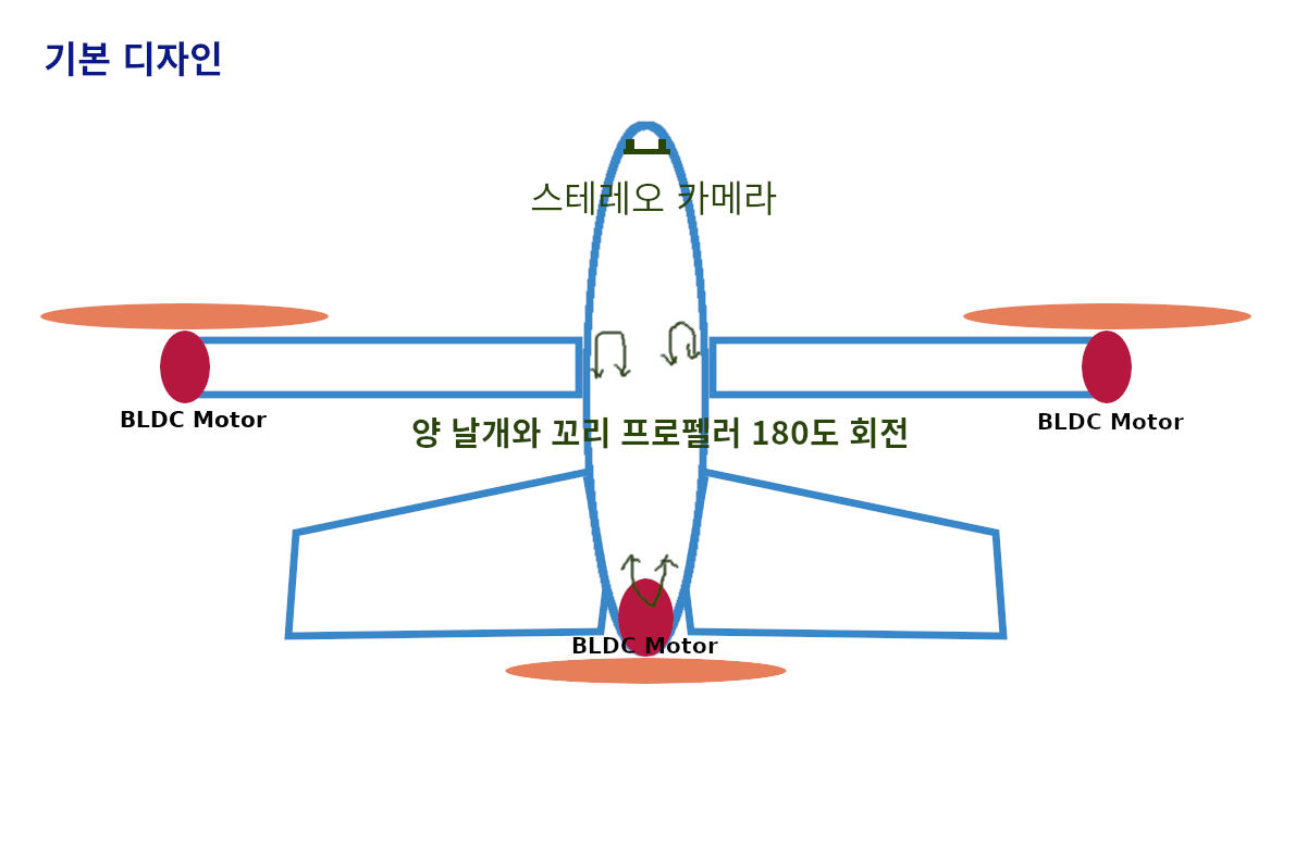
/*  This is written by Henry Kim, as a M.A.R. (Machine of Attack & Return)
   Currently testing level @ Oct. 1, 2023 
   
   3 ESC for Propellers
      - Center Tail Propeller
      - Left Wing Propeller
      - Right Wing Propeller
   3 Servo 메인 모터 180도 회전
      - for 180 degree rotation of 3 Propeller Motors
   10 LED
   1 A/D Battery Level Monitor
   1 A/D Light Sensor
   3 A/D Sound Sensor  
   1 A/D Temperature Sensor   
*/

#include <Servo.h>
#include "Parses.h"

// ---------------------------------------------------------------------------
// Customize here pulse lengths as needed
#define MIN_PULSE_LENGTH 1000 // Minimum pulse length in µs  (1 ms : min speed)
#define MAX_PULSE_LENGTH 2000 // Maximum pulse length in µs  (2 ms : max speed)

// ---------------------------------------------------------------------------
Servo escLeft1, escRight2, escCenter3;
Servo motLeft4, motRight5, motCenter6;

// ---------------------------------------------------------------------------

void setup() {   
   ClearCommand();
   
   Serial.begin(115200);
   Serial.println("#MAR-NANO>");

   // 3 main ESC for Props
   escLeft1.attach(4, MIN_PULSE_LENGTH, MAX_PULSE_LENGTH);
   escRight2.attach(5, MIN_PULSE_LENGTH, MAX_PULSE_LENGTH);
   escCenter3.attach(6, MIN_PULSE_LENGTH, MAX_PULSE_LENGTH);
   
   // Servos - Change angles of Prop motors
   motLeft4.attach(7);
   motRight5.attach(8);
   motCenter6.attach(9);

   // Prevent motor run at the start
   stopAllProps();  // set in MIN_PULSE_LENGTH
   
   // Servos heading top initially
   basePosition4Servos();  // Heading Top
   
}

void loop() {
   r++;   // 
   if (r > 300000) { r = 0; }   // Reset r if it is too large 
   if ((r % 20000) == 0) {      // Do some sensor reading
      //
   }
   
   while (Serial.available()) {
      inChar = (char)Serial.read(); 
      // get the new byte:
      //Serial.print(inChar);  // for debut
      // add it to the inputString:
      inputString[i] = inChar;
      i++;
      
      // if the incoming character is a newline, set a flag
      if (inChar == '<') {
         p2b_status = P2B_STAT_CMD;
         ClearCommand();
         j = i-1;         

      } else if (inChar == '>') {  // so the main loop can do something about it:

         p2b_command[0] = inputString[j+1]; // Get Command Character
         p2b_command[1] = inputString[j+2]; // Get Command Character
         p2b_command[2] = inputString[j+3]; // Get Command Character
         p2b_command[3] = inputString[j+4]; // Get Command Character
                                            // O : Orientation
                                            // D : Distance
         p2b_paramcount = int(inputString[j+6])-48; // take out 0
            
         j = j + 8;  // now j is pointing param starting position 
         if (p2b_paramcount > 0) {
            tempVal = 0; 
            nPos = 0;
            sign = 1;  // 1 = plus, -1 = minus
            k = 1;
            for (n=j;n<=lp+1;n++){
               // end of param 
               if ((inputString[n] == ',') or (inputString[n] == '>')){  
                  if (k == 1){
                     param1 = tempVal * sign;
                  }
                  if (k == 2){
                     param2 = tempVal * sign;
                  }
                  if (k == 3){
                     param3 = tempVal * sign;
                  }
                  if (k == 4){
                     param4 = tempVal * sign;
                  }
                  tempVal = 0; 
                  k++;  // Param No.
                  nPos = 0;
                  sign = 1;  // 1 = plus, -1 = minus
               } else {
                  if (inputString[n] == '-'){
                     sign = -1;
                  } else {
                     nPos++; 
                     if (nPos == 1) {
                        tempVal = (byte(inputString[n]) - 48); 
                     } else {
                        tempVal = tempVal * 10 + (byte(inputString[n]) - 48); 
                     }
                  }
               }
            }
         } // end of if command is for this Machine
         
         Serial.println("ESCT TEST 00"); 
         ExecuteLogicalCommand();   
         
         i = 100;  // refresh counter
         stringComplete = true;
         p2b_status = P2B_STAT_NONE;
            
      } else {
         lp = i-1;  // set last position on each entry;
      }
   }  /* while (Serial.available()) { */  
   if (stringComplete) {  
      uPrint();  // Return for debug
      ClearParamsAndInputstring(); 
   }
                    
}

void ExecuteLogicalCommand() {
   cmd = (char)p2b_command[0]+(char)p2b_command[1]+(char)p2b_command[2]+(char)p2b_command[3];
          
   if (cmd == "ESCT"){  // Test ESC for Prop Motors
      testESC(); 
   };
   if (cmd == "SRVT"){  // Test All Servos
      testServos();
   }

}

void basePosition4Servos(){
   // Servos heading top initially
   motLeft4.write(180);    // Heading Top
   motRight5.write(180);   // Heading Top
   motCenter6.write(180);  // Heading Top
}

void testServos()  // 3 Servos : escLeft1, escRight2, escCenter3
{
   // Heading top to bottom
   for (int i = 0; i <= 180; i += 10) {
      motLeft4.write(180-i);
      motRight5.write(180-i);
      motCenter6.write(180-i);      
      delay(100);
   // Heading bottom to top
   for (int i = 0; i <= 180; i += 10) {
      motLeft4.write(i);
      motRight5.write(i);
      motCenter6.write(i);      
      delay(100);
   }
   basePosition4Servos();
}

void stopAllProps() {
   escLeft1.writeMicroseconds(MIN_PULSE_LENGTH);
   escRight2.writeMicroseconds(MIN_PULSE_LENGTH);
   escCenter3.writeMicroseconds(MIN_PULSE_LENGTH);
}

void testESC()  // 3 ESC Test : escLeft1, escRight2, escCenter3
{
   for (int i = MIN_PULSE_LENGTH; i <= MAX_PULSE_LENGTH-700; i += 40) {
      // Serial.print("Pulse length = ");
      // Serial.println(i);
      escLeft1.writeMicroseconds(i);
      escRight2.writeMicroseconds(i);
      escCenter3.writeMicroseconds(i);      
      delay(200);
   }   
   stopAllProps();
}


초벌.  만들어 가면서 계속 수정 중임.


=========================


===================================================

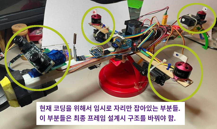
현재 기초 기능 코딩용 기체. 

(날개도 180도 움직이지 않는 고정형, 날개를 움직이는 서보는 그냥 따로 옆에 붙여서 컨트롤 실험만 한 후에 나중에 최종 프레임을 디자인 할 계획임.)


Objective : 

   1. Setting for headless mode (No monitor, mouse, keyboard) - remote access via TightVNCServer

   2. Minimal attachment to the board : power, webcam and network cable (switch to wifi dongle later).

   3. GPIO setting for motor control

   4. Serial communication with ESP32 (ESP32 will handle Lidar, A/D, DAC)


===========================================================

1. Download server image from Odroid wiki site.

2. For now, you cannot use SSH log-in.  So, attach monitor, keyboard, mouse.

3. After login, 

sudo passwd root
  (enter default password "odroid" for sudo)
  (for new password, "111" and confirm) - enter extremely easy password.  Save yourself from password hell.
  
sudo passwd odroid
  (same thing.  change all password to "111")

// This steps are needed for NPU to work
sudo apt update
sudo apt upgrade

sudo apt-get install nano

sudo nano /etc/ssh/sshd_config
// Allow enable SSH login option, so "root" can be remotely log-in
# Authentication:
#LoginGraceTime 2m
PermitRootLogin yes   (<== change right here)
#StrictModes yes
#MaxAuthTries 6
#MaxSessions 10

sudo reboot

// After reboot, make sure to log-in as root via SSH.  
// The user id "odroid" will not be used anymore.

// ************  IP RESERVATION with Router *************

// Try to reserve IP address for Odroid-M1 on your home or office router's configuration.

// If this device's MAC address is reserved with fixed local IP address, then this device will always have

// same local IP address everytime it boot-up.   In my case, I have set its IP to 192.168.1.96


// now log-in from PC using SSH as root, 111  (My case, I use Snowflake on Ubuntu.  With Snowflake, you can have file manager between PC & bot, text editor that can edit files on bot from PC, and endless number of terminals.)

// Install LXDE 

apt-get install lxde

  - during setting, it will as for gdm or lightdm, choose lightdm.

apt-get install libx11-dev libgtk2.0-dev libcairo2-dev libpango1.0-dev libxtst-dev libgdk-pixbuf2.0-dev libatk1.0-dev libghc-x11-dev
apt-get install xorg tango-icon-theme gnome-icon-theme


// Install Tight VNC Server

apt-get install tightvncserver thunar-volman udisks2 gvfs


// For NPU programming

apt install g++

apt install cmake


// Pre-install For Lazarus IDE

apt install gdb

apt-get install subversion


// For Webcam

apt-get install v4l-utils

apt-get install guvcview

apt-get install libgstreamer1.0-dev libgstreamer-plugins-base1.0-dev libgstreamer-plugins-bad1.0-dev gstreamer1.0-plugins-base gstreamer1.0-plugins-good gstreamer1.0-plugins-bad gstreamer1.0-plugins-ugly gstreamer1.0-libav gstreamer1.0-doc gstreamer1.0-tools gstreamer1.0-x gstreamer1.0-alsa gstreamer1.0-gl gstreamer1.0-gtk3 gstreamer1.0-qt5 gstreamer1.0-pulseaudio


// For general programming

apt-get install -y git


// For general monitoring

apt-get install htop


// GPIO library : How to download wiringOP
apt install odroid-wiringpi
apt install wiringpi-examples
gpio readall
gpio readall -a


// Disable auto hibernate.   It is extremely annoying if it keeps on hibernating and never wakes up.

systemctl mask sleep.target suspend.target hibernate.target hybrid-sleep.target


ip addr   <== to find out the local IP address of  Odroid-M1.  In my case, I have fixed its IP to 192.168.1.96 at router.


// Remote Log-in via VNC with Remmina Remote Desktop

tightvncserver

  - then it will ask for vnc remote password two times.   Enter "111" for simplicity

  - Would you like to enter a view-only password (y/n)?  <= Important.  You don't want view-only.


// Using Remmina from Ubuntu PC, log-in with VNC with the local IP address + ":1" at the end.

// Once you log-in via VNC, then now, you are READY! to run it in headless mode and develop Robot.

VNC remote log-in


I love this style, similar to old Windows 95.&nbsp; &nbsp; Perform USB webcam test with guvcview

===============================================================

NPU CAM demo (I have done it with UBS webcam.)

For this demo, you will have to follow the instruction from wiki site's RKNPU  project.

Important : If server image is used instead of desktop image, OpenCV must be installed from source in order to make this demo work.   

Otherwise, ./build-linux.sh step will terminate with error.

Refer this site for installing OpenCV from source - (Method 2) :  vitux.com/opencv_ubuntu/


좋은 출처 : https://www.electronicwings.com/raspberry-pi/mpu6050-accelerometergyroscope-interfacing-with-raspberry-pi


MPU6050 (Accelerometer+Gyroscope) Interfacing with Raspberry Pi |..

MPU6050 is a combination of 3-axis Gyroscope, 3-axis Accelerometer and Temperature sensor with on-board Digital Motion Processor (DMP). It is used in mobile devices, motion enabled games, 3D mice, Gesture (motion command) technology etc.

www.electronicwings.com

MPU6050 Code for Raspberry Pi using Python 

'''
        Read Gyro and Accelerometer by Interfacing Raspberry Pi with MPU6050 using Python
	http://www.electronicwings.com
'''
import smbus				#import SMBus module of I2C
from time import sleep        #import

#some MPU6050 Registers and their Address
PWR_MGMT_1   = 0x6B
SMPLRT_DIV   = 0x19
CONFIG       = 0x1A
GYRO_CONFIG  = 0x1B
INT_ENABLE   = 0x38
ACCEL_XOUT_H = 0x3B
ACCEL_YOUT_H = 0x3D
ACCEL_ZOUT_H = 0x3F
GYRO_XOUT_H  = 0x43
GYRO_YOUT_H  = 0x45
GYRO_ZOUT_H  = 0x47


def MPU_Init():
	#write to sample rate register
	bus.write_byte_data(Device_Address, SMPLRT_DIV, 7)
	
	#Write to power management register
	bus.write_byte_data(Device_Address, PWR_MGMT_1, 1)
	
	#Write to Configuration register
	bus.write_byte_data(Device_Address, CONFIG, 0)
	
	#Write to Gyro configuration register
	bus.write_byte_data(Device_Address, GYRO_CONFIG, 24)
	
	#Write to interrupt enable register
	bus.write_byte_data(Device_Address, INT_ENABLE, 1)

def read_raw_data(addr):
	#Accelero and Gyro value are 16-bit
        high = bus.read_byte_data(Device_Address, addr)
        low = bus.read_byte_data(Device_Address, addr+1)
    
        #concatenate higher and lower value
        value = ((high << 8) | low)
        
        #to get signed value from mpu6050
        if(value > 32768):
                value = value - 65536
        return value


bus = smbus.SMBus(5) 	# or bus = smbus.SMBus(0) for older version boards
Device_Address = 0x68   # MPU6050 device address

MPU_Init()

print (" Reading Data of Gyroscope and Accelerometer")

while True:
	
	#Read Accelerometer raw value
	acc_x = read_raw_data(ACCEL_XOUT_H)
	acc_y = read_raw_data(ACCEL_YOUT_H)
	acc_z = read_raw_data(ACCEL_ZOUT_H)
	
	#Read Gyroscope raw value
	gyro_x = read_raw_data(GYRO_XOUT_H)
	gyro_y = read_raw_data(GYRO_YOUT_H)
	gyro_z = read_raw_data(GYRO_ZOUT_H)
	
	#Full scale range +/- 250 degree/C as per sensitivity scale factor
	Ax = acc_x/16384.0
	Ay = acc_y/16384.0
	Az = acc_z/16384.0
	
	Gx = gyro_x/131.0
	Gy = gyro_y/131.0
	Gz = gyro_z/131.0
	

	print ("Gx=%.2f" %Gx, u'\u00b0'+ "/s", "\tGy=%.2f" %Gy, u'\u00b0'+ "/s", "\tGz=%.2f" %Gz, u'\u00b0'+ "/s", "\tAx=%.2f g" %Ax, "\tAy=%.2f g" %Ay, "\tAz=%.2f g" %Az) 	
	sleep(1)

Code 실행 결과 

 Reading Data of Gyroscope and Accelerometer
Gx=0.00 °/s     Gy=0.00 °/s     Gz=0.00 °/s     Ax=0.00 g       Ay=0.00 g       Az=0.00 g
Gx=-0.25 °/s    Gy=-0.05 °/s    Gz=-0.04 °/s    Ax=-0.18 g      Ay=0.56 g       Az=0.72 g
Gx=-0.28 °/s    Gy=-0.10 °/s    Gz=-0.02 °/s    Ax=-0.17 g      Ay=0.56 g       Az=0.74 g
Gx=21.01 °/s    Gy=-46.73 °/s   Gz=-66.13 °/s   Ax=-0.60 g      Ay=0.53 g       Az=1.98 g
Gx=-1.12 °/s    Gy=0.08 °/s     Gz=-2.44 °/s    Ax=0.91 g       Ay=0.25 g       Az=-0.42 g
Gx=-20.89 °/s   Gy=22.92 °/s    Gz=-12.68 °/s   Ax=0.57 g       Ay=0.91 g       Az=-0.08 g
Gx=-8.25 °/s    Gy=6.10 °/s     Gz=-2.79 °/s    Ax=-0.14 g      Ay=-0.28 g      Az=0.79 g
Gx=0.19 °/s     Gy=-1.33 °/s    Gz=0.41 °/s     Ax=-0.27 g      Ay=-0.19 g      Az=0.89 g
Gx=-1.12 °/s    Gy=0.74 °/s     Gz=-1.82 °/s    Ax=0.01 g       Ay=-0.03 g      Az=0.93 g
Gx=-16.98 °/s   Gy=-8.69 °/s    Gz=-0.35 °/s    Ax=0.53 g       Ay=0.11 g       Az=0.41 g
Gx=-0.86 °/s    Gy=-3.69 °/s    Gz=-3.56 °/s    Ax=0.41 g       Ay=-0.85 g      Az=1.86 g
Gx=8.50 °/s     Gy=-13.91 °/s   Gz=-2.17 °/s    Ax=1.00 g       Ay=0.22 g       Az=-0.11 g
Gx=1.95 °/s     Gy=-15.69 °/s   Gz=-6.44 °/s    Ax=0.88 g       Ay=0.49 g       Az=0.22 g
Gx=-0.90 °/s    Gy=-19.22 °/s   Gz=4.11 °/s     Ax=0.79 g       Ay=0.20 g       Az=0.20 g
Gx=2.63 °/s     Gy=-0.53 °/s    Gz=3.50 °/s     Ax=0.57 g       Ay=0.22 g       Az=0.47 g
Gx=7.98 °/s     Gy=-5.44 °/s    Gz=-4.53 °/s    Ax=0.16 g       Ay=-0.44 g      Az=1.19 g
Gx=-1.49 °/s    Gy=2.40 °/s     Gz=-1.51 °/s    Ax=0.50 g       Ay=-0.40 g      Az=0.69 g
Gx=9.06 °/s     Gy=-0.34 °/s    Gz=11.00 °/s    Ax=-0.20 g      Ay=-0.04 g      Az=0.61 g
Gx=8.08 °/s     Gy=-0.40 °/s    Gz=-2.18 °/s    Ax=-0.12 g      Ay=0.08 g       Az=0.93 g
Gx=-0.26 °/s    Gy=-0.06 °/s    Gz=-0.07 °/s    Ax=-0.04 g      Ay=0.12 g       Az=0.94 g
Gx=-0.23 °/s    Gy=-0.02 °/s    Gz=-0.08 °/s    Ax=-0.04 g      Ay=0.12 g       Az=0.94 g
Gx=-0.25 °/s    Gy=-0.08 °/s    Gz=-0.09 °/s    Ax=-0.06 g      Ay=0.15 g       Az=0.93 g
Gx=-0.23 °/s    Gy=-0.05 °/s    Gz=-0.03 °/s    Ax=-0.06 g      Ay=0.17 g       Az=0.93 g
Gx=-0.29 °/s    Gy=-0.06 °/s    Gz=-0.05 °/s    Ax=-0.07 g      Ay=0.15 g       Az=0.92 g
Gx=-0.40 °/s    Gy=0.06 °/s     Gz=-0.11 °/s    Ax=-0.07 g      Ay=0.16 g       Az=0.94 g
Gx=-0.28 °/s    Gy=-0.04 °/s    Gz=-0.08 °/s    Ax=-0.08 g      Ay=0.17 g       Az=0.93 g
Gx=-0.25 °/s    Gy=-0.07 °/s    Gz=-0.04 °/s    Ax=-0.06 g      Ay=0.14 g       Az=0.94 g
Gx=-0.27 °/s    Gy=-0.05 °/s    Gz=-0.02 °/s    Ax=-0.06 g      Ay=0.16 g       Az=0.93 g
Gx=6.27 °/s     Gy=8.89 °/s     Gz=2.79 °/s     Ax=0.06 g       Ay=-0.07 g      Az=0.90 g
Gx=4.08 °/s     Gy=36.98 °/s    Gz=-14.33 °/s   Ax=0.28 g       Ay=0.08 g       Az=0.66 g
Gx=-2.27 °/s    Gy=-2.36 °/s    Gz=-1.52 °/s    Ax=-0.13 g      Ay=0.01 g       Az=0.95 g
Gx=0.41 °/s     Gy=-0.18 °/s    Gz=-0.15 °/s    Ax=-0.09 g      Ay=0.30 g       Az=0.89 g
^CTraceback (most recent call last):
  File "/root/o/2.py", line 82, in <module>
    sleep(1)


원본 영상 : youtu.be/AwRrOxVjAWE 

윗 영상의 코드를 직접 따라 해 봤습니다.  아무래도 원본에 에러가 있는 듯 한데 직접 고쳤습니다.

윗 영상은 저처럼 파이션이 낯선 사람들이 공부용으로는 좋은데 로봇 이미지와 코드는 무료가 아닙니다.

이건 제가 직접 만든 로봇 이미지와 입력한 코드입니다. (Zip 화일로 올려놓았습니다)

설명을 들으면서 치다보니 pygame에 익숙해 지는 느낌이라 오히려 좋았습니다.

following_robot.zip
0.08MB


# File name : difdrive.py
# Link : https://www.youtube.com/watch?v=zHboXMY45YU
# Download Car image & rename to DDR.png : https://imgur.com/SpeVm6L 
# x1 = v*cos(theta)
# y1 = v*sin(theta)
# Theta1 = diff(v) / W

import pygame
import math

class Envir:
   def __init__(self, dimensions):
      # colours
      self.black = (0, 0, 0)
      self.white = (255, 255, 255)
      self.green = (0, 255, 0)
      self.blue  = (0, 0, 255)
      self.red   = (255, 0, 0)
      self.yel   = (70, 70, 70)
      # map dimensions
      self.height = dimensions[0]
      self.width  = dimensions[1]
      # window settings
      pygame.display.set_caption("Differential drive robot")
      self.map = pygame.display.set_mode((self.width, self.height))
      # text variables
      self.font = pygame.font.Font('freesansbold.ttf', 50)
      self.text = self.font.render('default', True, self.white, self.black)
      self.textRect = self.text.get_rect()
      self.textRect.center = (dimensions[1] - 600,
                              dimensions[0] - 100)
      #trail
      self.trail_set=[]                        
                              
   def write_info(self, Vl, Vr, theta):
      txt = f"Vl = {Vl} Vr = {Vr}  theta = {int(math.degrees(theta))}"
      self.text = self.font.render(txt, True, self.white, self.black)
      self.map.blit(self.text, self.textRect)
      
   def trail(self, pos):
      for i in range(0, len(self.trail_set)-1):
         pygame.draw.line(self.map, self.yel, 
            (self.trail_set[i][0], self.trail_set[i][1]),
            (self.trail_set[i+1][0], self.trail_set[i+1][1]))
      if self.trail_set.__sizeof__() > 10000:
         self.trail_set.pop(0)
      self.trail_set.append(pos)   
      
   def robot_frame(self, pos, rotation):
      n = 80
      
      centerx, centery = pos
      x_axis = (centerx + n * math.cos(-rotation), centery + n * math.sin(-rotation))
      y_axis = (centerx + n * math.cos(-rotation + math.pi/2), 
                centery + n * math.sin(-rotation + math.pi/2))
      pygame.draw.line(self.map, self.red, (centerx, centery), x_axis, 3)
      pygame.draw.line(self.map, self.green, (centerx, centery), y_axis, 3)      
                 
class Robot:
   def __init__(self, startpos, robotImg, width):
      self.m2p = 3779.52  # meters to pixels ratio
      # robot dimensions
      self.w = width
      self.x = startpos[0]
      self.y = startpos[1]
      self.theta = 0
      self.vl = 0.01 * self.m2p  # meters / second
      self.vr = 0.01 * self.m2p  # meters / second
      self.maxspeed = 0.02 * self.m2p
      self.minspeed = -0.02 * self.m2p
      # graphics
      self.img = pygame.image.load(robotImg)
      self.rotated = self.img
      self.rect=self.rotated.get_rect(center=(self.x, self.y))
      
   def draw(self, map):
      map.blit(self.rotated, self.rect)   
      
   def move(self, event=None):
      if event is not None:
         if event.type == pygame.KEYDOWN:
            if event.key == pygame.K_KP4:  # Left Arrow in Numpad     
               self.vl += 0.001 * self.m2p
            elif event.key == pygame.K_KP1:  # 1  
               self.vl -= 0.001 * self.m2p    
            elif event.key == pygame.K_KP6:  # Right Arrow in Numpad  
               self.vr += 0.001 * self.m2p
            elif event.key == pygame.K_KP3:  # 3  
               self.vr -= 0.001 * self.m2p
               
      # v=(Vr+Vl)/2                  
      self.x += ((self.vl + self.vr) / 2) * math.cos(self.theta) * dt   
      self.y -= ((self.vl + self.vr) / 2) * math.sin(self.theta) * dt
      self.theta += (self.vr - self.vl) / self.w * dt
      # reset theta
      if self.theta > 2 * math.pi or self.theta < -2 * math.pi :
         self.theta = 0
      # set max speed
      self.vr = min(self.vr, self.maxspeed)
      self.vl = min(self.vl, self.maxspeed)
      # set min speed      
      self.vr = max(self.vr, self.minspeed)
      self.vl = max(self.vl, self.minspeed)
      
      self.rotated = pygame.transform.rotozoom(self.img,
         math.degrees(self.theta), 1)         
      self.rect = self.rotated.get_rect(center=(self.x, self.y))


# initialization
pygame.init()

# start postion
start = (200, 200)

# dimension
dims=(600, 1200)

# running or not
running = True

# the envir
environment = Envir(dims)

# the Robot (begining location, image of robot, width)
robot = Robot(start, "./DDR.png", 0.01 * 3779.52)

# dt (Change in time)
dt = 0
lasttime = pygame.time.get_ticks()

# simulation loop
while running:
   for event in pygame.event.get():
      if event.type == pygame.QUIT:
         running = False
      robot.move(event)
       
   dt = (pygame.time.get_ticks()-lasttime) / 1000     
   lasttime = pygame.time.get_ticks()
   pygame.display.update()
   environment.map.fill(environment.black)
   robot.move()
   environment.write_info(int(robot.vl),
                          int(robot.vr),
                          robot.theta)
   robot.draw(environment.map)          
   environment.trail((robot.x, robot.y))             
   environment.robot_frame((robot.x, robot.y), robot.theta)
                              
   #if pygame.mouse.get_focused():
      #sensorOn = True

+ Recent posts